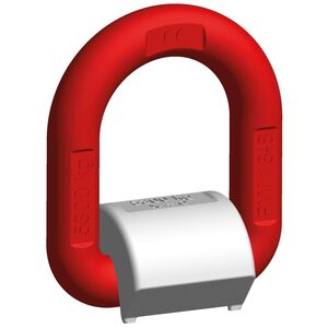
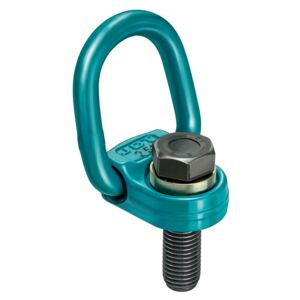
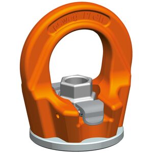
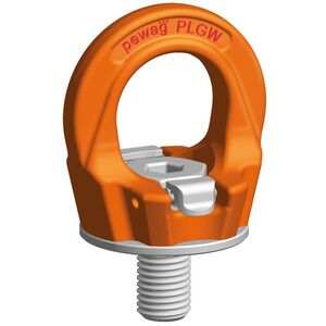
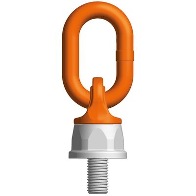
Ball-bearing 360° under load rotatable lifting point. High resistant lifting eye 180° movable. The special screws are 100% crack-tested as well as protected against corrosion. The table with the load capacities depending on the method of lifting as lifting gear, number of legs and angle of inclination is a part of the user manual and packed together with each lifting point.
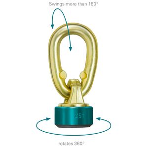
Permissible usage
Load capacity acc. to the inspection certificate respectively table of WLL in the mentioned directions of pull (see picture 1).
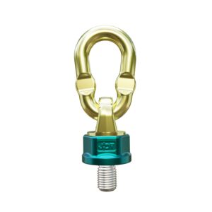
Non permissible usage
Make sure when choosing the assembly that improper load can not arise e.g. if:
- The direction of pull is obstructed
- Direction of pull is not in the foreseen area (see picture 2)
- Loading ring rests against edges or load
To calculate the necessary thread length (L):
L = H + S + K + X
H = Material height
S = Thickness of the washer
K = Height of the nut (depending on the thread size of the screw)
X = Excess length of the screw (twofold pitch of the screw)
L max. = n max.
- Material: Alloy steel grade 10.
- Marking: WLL, thread size and an individual serial number.
- Note: Also available in special length (SL) and maximum lenght (MAXL) as well.
- Safety factor: 4:1
- Grade: 10


Download CAD

Download CAD by choosing the desired product from the table above and the format from the menu below. Click "Get CAD" and after the load reaches 100% you can click on the download icon to download it. Please note that CAD drawings are only available if the icon at the right side of the table above is colored and not grayed out.
Method of lifting
|
|
|
|
|
|
|
|
|
|
|
![]() |
|
|
||||||||||
Number of legs
|
|
|
1
|
1
|
2
|
2
|
2
|
2
|
3+4
|
3+4
|
2 |
3+4
|
|
||||||||||
Angle of inclination
|
|
|
0°
|
90°
|
0°
|
90°
|
0°-45°
|
45°-60°
|
0°-45°
|
45°-60°
|
asymm. |
asymm.
|
|||||||||||
Code
|
Thread
|
Fastening torque
|
Load capacity
|
|
|
|
|
|
|
|
|
|
|||||||||||
|
mm
|
Nm
|
tons
|
mm |
|
|
|
|
|
|
|
|
|
||||||||||
PLDW M8
|
M8
|
10
|
0,6
|
0,3
|
1,2
|
0,6
|
0,4
|
0,3
|
0,6
|
0,4
|
0,3
|
0,3
|
34 | ||||||||||
PLDW M10
|
M10
|
10
|
1
|
0,5
|
2
|
1
|
0,7
|
0,5
|
1
|
0,75
|
0,5
|
0,5
|
34 | ||||||||||
PLDW M12
|
M12
|
15
|
1,4
|
0,7
|
2,8 |
1,4
|
0,95
|
0,7
|
1,4
|
1
|
0,7
|
0,7
|
34 | ||||||||||
PLDW M14
|
M14
|
25
|
2
|
1
|
4
|
2
|
1,4
|
1
|
2,1
|
1,5
|
1
|
1
|
34 | ||||||||||
PLDW M16
|
M16
|
30
|
2,8
|
1,5
|
5,6
|
3
|
2,1
|
1,5
|
3,1
|
2,1
|
1,5
|
1,5
|
34 | ||||||||||
PLDW M20
|
M20
|
80
|
5
|
2,5
|
10
|
5
|
3,5
|
2,5
|
5,3
|
3,5
|
2,5
|
2,5
|
46 | ||||||||||
PLDW M24
|
M24
|
150
|
7
|
4
|
14
|
8
|
5,5
|
4
|
8,4
|
6
|
4
|
4
|
50 | ||||||||||
PLDW M30
|
M30
|
230
|
10
|
6,7
|
20
|
13.4
|
9,4
|
6,7
|
14,2 | 10 |
6,7
|
6,7
|
60 | ||||||||||
PLDW M36
|
M36
|
450
|
12,5
|
8
|
25
|
16
|
11,2
|
8
|
16,8
|
12
|
8
|
8
|
75 | ||||||||||
PLDW M42
|
M42
|
600
|
16
|
10
|
32
|
20
|
14
|
10
|
21
|
15
|
10
|
10
|
75 | ||||||||||
PLDW M45
|
M45
|
600
|
16
|
12
|
32
|
24
|
16,9
|
12
|
25,4
|
18
|
12
|
12
|
75 | ||||||||||
PLDW M48
|
M48
|
600
|
16
|
12,5
|
32
|
25
|
17,5
|
12,5
|
26,2
|
18
|
12,5
|
12,5
|
75 | ||||||||||
PLDW M56
|
M56
|
800
|
28
|
24
|
56
|
48
|
33,9
|
24
|
50,9
|
36
|
24
|
24
|
95 | ||||||||||
PLDW M64
|
M64
|
800
|
28
|
25
|
56
|
50
|
35,3
|
25
|
53
|
37,5
|
25
|
25
|
95 | ||||||||||
PLDW M72
|
M72
|
1200
|
60
|
40
|
120
|
80
|
56,5
|
40
|
84,8
|
60
|
40
|
40
|
145 | ||||||||||
PLDW M80
|
M80
|
1400
|
60
|
45
|
120
|
90
|
63,6
|
45
|
95,4
|
67,5
|
45
|
45
|
145 |